Friday, April 29, 2011

Node navigation and resizing secrets

Today I will talk about some unspoken secrets about navigating and resizing nodes in mental mill 1.1. The nodes in mental mill can be navigated and resized in a much more sophisticated way than most users might think, so I will share those secrets with you today!

Hiding input and output parameters
Hold down the shift-key and resize the top or the bottom of your node. This will conceal the input or ouput parameter section of a node.

Scrolling within a node that is partly concealed
When a node has been changed so that either parts of the input- or output parameter section are not visible, a light gray scroll bar appears on the side. For input parameters, the scroll bar will appear on the right side, output parameters can be scrolled on the right side.

Collapsing a node
You can collapse a node all the way: Hold the shift key and drag the top or bottom border of the node so that it is entirely collapsed . This is very useful when you have nodes on your workspace that don't play an important role and that you don't want to clutter up your view. If you have got any other nodes connected, you can see that the connection wires are made semi-transparent.

Scrolling a party collapsed node / Restoring a node
  1. Double-click the Top or Bottom bar of a node to restore its default view.
  2. You can use the scroll bars to scroll within an input or output parameter section that is partly concealed
  3. When the node is in a semi-collapsed state, you can left-click and drag the splitter bar in the middle to hide and reveal the input parameter section.

Resizing preview windows
  • The preview windows of the output parameters of a node can be resized individually: Click and drag one of the corners of the preview window.
  • Preview windows can be opened and closed by left-clicking the name of the output parameter.

Friday, April 1, 2011

Procedural patterns using mental mill 1d Curve Shaders

Motivation
In the previous post I explained how you can create a ray pattern effect using basis mental mill nodes. This involved some math operations and it took a couple of nodes to make the effect work. We want to achieve the 
same result in a simpler way, so next I show you how to use the curve nodes that come with mental mill curve shader pack.
This pack includes nodes that generate one dimensional curves which can be used to drive shader parameters, remap values and colors and generate textures and patterns.

When you use those curve nodes for the first time you might get the feeling that this whole concept is a bit abstract, so I would like to give you an idea of how versatile these shaders really are and I will show one use case.

Curve Shapes

Curve shaders are able to generate curves of all kinds of shapes. Basically they implement a mathematical functions of the style y=f(x) which means that for a given input value X an output value Y is computed. The curve shader nodes were designed that you are able to see the curves graphically by opening the "graph_out" parameter of a curve node. 


Curves can be used to generate patterns using the "gradient_linear" and "gradient_radial" nodes.
Here you can see which kinds of curves you can generate

Angular and radial gradient - the boolean
switch allows to change the generation behavior
Let's try that: Just attach a curve shader to the 'curve' input of the gradient_radial node. You can change the way that the pattern is generated by enabling the boolean parameter 'Circular' which will generate a circular pattern.

Try different curves and you see how the generated texture changes. If you want to create a fancy ray pattern, use the noise_1d curve which gives you a 
large number of animatable parameters to generate random looking rays.

Adding variation

Now you know how to generate basic patterns. It gets more interesting when you start sidechaining other gradient nodes which I will show in the next steps:

The gradient_radial node has an input parameter 'offset'. Create another gradient_radial node, convert it to a float value and attach it to the 'offset' parameter of the first gradient_radial node: You see that it generates a spiral now.


I guess now you know where we will be going with this example: The offset is now driven by another gradient node. So what happens if we attach another curve generator to the second gradient node? Let's try that:


You see that the offset is too strong and that it's only offsetting in one direction because we feed only positive values to the offset. So let's change the range using a Math_float_lerp node. (Remember: A lerp nodes interpolates incoming values that ramge from 0 to 1 to range from 'start' to 'end' so that 0 is mapped to 'start' and 1 is mapped to 'end'. Values outside that range are extrapolated. )


Now the offset gives some really interesting result which we can further elaborate on by animating it. So lets add some animation on top:

Create a state_animation_time and send it to a math_float_multiply so that you can adjust the speed of the animation. Connect the result to the offset parameter of the second generator node.

Start the animation now and see, how the ray pattern is animated now.

From there you get the idea how you can create arbitrarily complex patterns by combining several gradients that drive other gradients.

Conclusion:
In case you need to create fancy ray patterns for some retro-70ies effect, you now know what you need. Though I'd expect you won't need to create this kind of procedural patterns too often, you get an idea of how you can use curve nodes to create different kinds of gradients. Driving one gradient with the result of another gradient node and adding animation on top allows you to create sophisticated effects.

Curve nodes allow you to create much more interesting effects and there are more use cases - I intend to show more in another post.

Have fun creating your own fancy patterns and playing around with them!

Thursday, March 24, 2011

Ray pattern effect using basic mental mill shaders


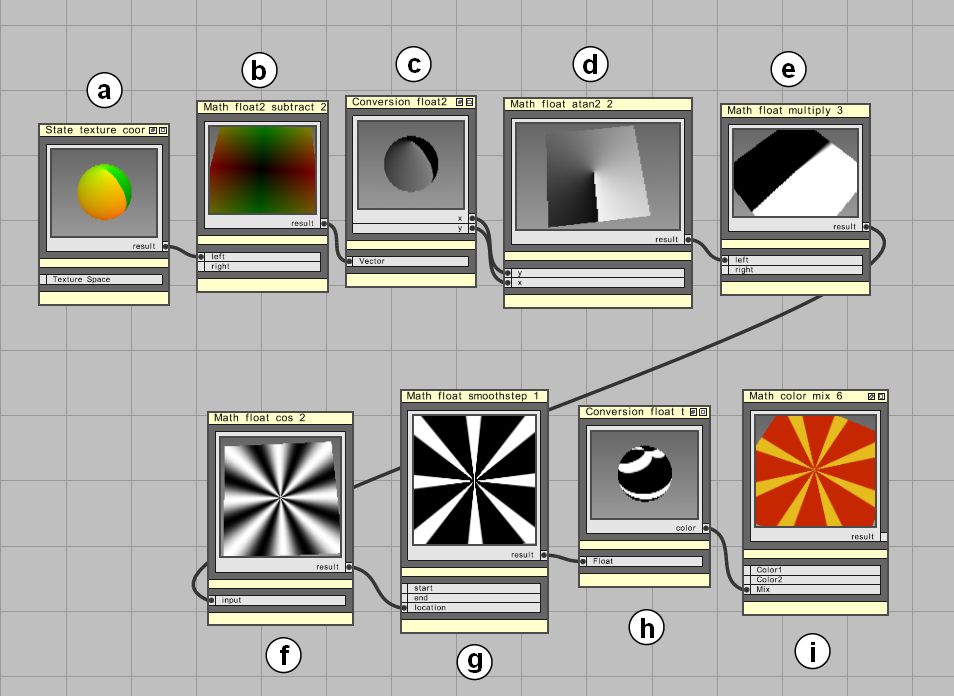
This time I assembled an example that shows how to create a kind of funky sunbeam-effect using the MetaSL shaders. I won't go too much into the details this time. I tried to make the project quite self-explaining. Just start at the top of the workspace where you can see some nodes connected. This is the basic idea of how the ray pattern is created. Further down in the workspace you can find several Phenomena that extend the ray pattern effect. Later I will show you how you can achieve the same effect much easier using the MetaSL curve shaders.


You can find the mental mill project here.


The texture space is offset so that it ranges from -0.5 to +0.5 (a and b). The u and v components are split (c) and then fed into a Math_float_atan2 (d) node. This returns values that range from -PI to +PI. By multiplying this with an integer (e) (well actually it is a float, i guess you know what I mean) and feeding it into a Math_float_cos node (f) you get a result that ranges from -1 to +1 and creates the ray pattern.


To shape the rays I used a Math_float_smoothstep (g) node. The result of the cosine-node is fed into the 'locaction' input of the Math_float_smoothstep node. For the input parameters 'start' and 'end' use values that are close to each other to get a crisper transition. Applicable ranges are between -1 and +1.


Finally the resulting float value is converted to a color (h) and fed into the mix parameter of a Math_color_mix node (i) that you can use to mix two different colors.


Next I will show you how to use the MetaSL curve shaders to achieve the same effect but faster and in a more versatile way.

Tuesday, March 22, 2011

GDC 2011

Recently we have been at the GDC in San Francisco which has been a really great show. As usual we have been showing off mental mill at the NVidia booth where we were demoing the latest version of mental mill, namely an early version of 1.2.
Unfortunately my pocket camera did not work too well under the lighting conditions on the showfloor, so there are no good images to show, unfortunately. However, I got one shot of David explaining the software to an interested person.

We gave a preview of the new features that have been added to mental mill 1.2 and it was interesting to discuss with the users and hear their feedback. For those who have not been at the GDC, here are some of the highlights that we were showing:


  • scene element nodes: In version 1.2 there are new node types that describe a scene that can be previewed inside mental mill. These include the description of geometry, lights and a camera.
  • Load any number of preview objects and apply different shaders to them
  • View all geometry in one  scene (which is practical if you have a model that is made out of several pieces of geometry that need different shaders)
  • Render previews with iray and mental ray directly inside the camera node on the workspace. No need to launch a separate render window.
  • Shader creation for iray: iray supports a subset of shaders that you can easily wire up in mental mill and render it with iray inside the camera node
  • Project manager: The project manager helps to keep an overview over the shader files and shaders used in your project which helps you to keep an overview over your shader assets.
For our demos we were kindly provided with models by The Game Assembly which has some talented artists that created some cool models. Thanks for their collaboration, I hope to post some images soon. 

Monday, March 21, 2011

MetaSL webpage online

Today the the website www.metasl.org went online. For all those mental mill users who are interested in writing their own shaders, this is a comprehensive resource that helps to quickly get an idea of how to use MetaSL.

Right now the webpage is work in progress. For now you can find the first four chapters which are also available as PDF downloads for reading offline. These are draft versions of chapters and might be changed and updated.
New chapters will be added in the next weeks.

The chapters so far are:


  • Chapter 1: MetaSL — Strategy and scope
  • Chapter 2: Elements of the MetaSL language
  • Chapter 3: Basic surface shaders
  • Chapter 4: Rendering state


MetaSL is a platform independent shading language that can be translated to any existing target shading language. This makes it extremely useful if you need to deploy your shader on multiple platforms. Furthermore, you need to write your shader only once, allowing you to concentrate on the algorithmic aspect of your code rather than porting it manually from one language to another.

For sending feedback, you can take a look at the MetaSL Book open forum where you can leave your message and discuss with others.

Friday, December 31, 2010

Blurred environment reflection

Here is a shader that is intended for real time usage. It takes advantage of passing custom derivatives to the texture lookup function. This is quite useful to produce blurred environment lookups. This enables you to produce more realistic looking surfaces because it allows you to mimic real-world surfaces in a much better way.

Since it is the 31st of December and I am about to dive into the next new year's party I will keep this post short... ;)

Idea:
Create an shader for real time usage that blurs the reflection based on the incident viewing direction.

Different Blurs of the reflection:
  • From inner to outer 
  • from outer to inner 
  • controlled by another texture

Observation:

  • If you take a look at a blurry surface, the reflection gets crisper when you look at it from a grazing angle. I observated this in detail a couple of years ago when I was working at a post production company and we were doing a promotion video for a big steel industry company.
    My colleagues back then told me that I was too meticulous. Maybe I was, but when your passion is building shader graphs its the observation and implementation of these small details that give the extra punch to your shader.
  • Also, reflections appear to have less saturation which, depending on the surface is not true. However, I added a control to the shader that allows you to drive the saturation of the lookup.


Other features:

  • The environment blur can be inverted
  • A constant blur can be applied too
  • Amount of the incident blur can be controlled

Tip:

  • Use the constant blur to shift the incident blur
Find the shader code on the mental images forum

Increasing the intensity of the constant blur (controlled by a texture) can yield
stunning looking corrosion effects. Also the reflection saturation has been
reduced for these screenshots.

Happy New Year Everyone!

Thursday, December 30, 2010

Uncharted 2 Art Direction

As shader artist, you have to work closely with other designers, modelers, art directors all of which have a different view of their profession. When it comes to creating big game titles, I am in awe how good these groups can work together to produce these marvelous wonderlands that take us to new places that don't even exist in the real world.
A friend of mine forwarded me this link that gives insight in the art direction of the game "Uncharted 2". Though I haven't played the game, the document is very interesting and can give you some insight and good inspiration. Take a look.

Art Direction in Uncharted 2